Sensorless BLDC Motor Controller
A custom six-step sensorless BLDC controller using back-EMF zero-crossing detection, PWM commutation, dead time, current sensing, and temperature protection on a Teensy 4.1.
Role
Sole designer & firmware developer
Team
Individual
Status
In Development
Timeline
2026 – Present
Board
BLDC Motor Controller
Revision
Rev A
Layers
2-layer
Dimensions
80 × 60 mm
- ▹Six-MOSFET three-phase inverter
- ▹Gate-driver design with dead time
- ▹Floating-phase back-EMF zero-crossing detection
- ▹Current and temperature protection
- ▹Custom PCB designed in KiCad
- ▹Approximately 20 kHz PWM
Problem Statement
Sensorless BLDC drives reduce cost and wiring complexity by eliminating Hall sensors, but they require careful analog front-end design and timing-critical firmware to reconstruct rotor position from back-EMF.
This project builds a self-contained controller that can start, accelerate, and regulate a BLDC motor using six-step commutation derived from floating-phase zero-crossing events.
Design Goals
- Reliable six-step sensorless commutation
- Gate-drive stage with intentional dead time
- Over-current and over-temperature protection
- ~20 kHz PWM suitable for small BLDC motors
- Bring-up path that is measurable on a lab bench (scope, current probe)
System Architecture
The system is organized as:
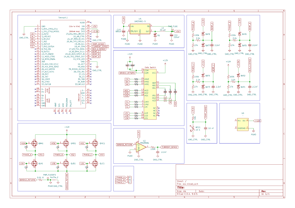
- Power stage — six-MOSFET three-phase inverter
- Gate drivers — isolated/level-shifted drive with dead-time enforcement
- Sense chain — floating-phase back-EMF dividers, shunt current sense, temperature sensor
- Controller — Teensy 4.1 running PWM timers, ADC sampling, and commutation state machine
Commutation advances on predicted or measured zero-crossings with a 30° electrical delay typical of six-step sensorless schemes.
Hardware Design
The custom KiCad PCB integrates the inverter, gate drivers, sensing networks, and Teensy interface.
Key hardware choices: - Discrete MOSFET half-bridges sized for prototype current - Resistive dividers for floating-phase back-EMF measurement - Shunt-based current sensing into the ADC - Temperature monitoring for thermal shutdown
*[Placeholder: replace with annotated PCB screenshots and schematic excerpts.]*
Software Design
Firmware is structured as a real-time control loop:
- PWM generation with complementary outputs and dead time
- ADC sampling synchronized to PWM edges where possible
- Zero-crossing detection and commutation advance
- Fault handling for over-current / over-temperature
Open-loop start-up ramps into closed-loop sensorless tracking once back-EMF amplitude is usable.
Engineering Decisions
- Six-step over FOC for a clearer bring-up path and educational transparency of back-EMF sensing
- Teensy 4.1 for fast timers, plenty of PWM channels, and easy bench iteration
- Discrete inverter to keep the power path inspectable and easy to probe
Testing and Validation
Planned / in-progress validation: - Gate waveforms and dead-time verification on a scope - Back-EMF waveform capture on a spinning motor - Current-limit trip testing with a current-limited supply - Thermal soak under load
*[Placeholder: add scope captures and test logs as they become available.]*
Results
Project is currently in development. Early bring-up focuses on reliable open-loop spin-up and clean zero-crossing detection before closed-loop speed control.
Challenges
- Distinguishing true zero-crossings from PWM switching noise
- Stable start-up before back-EMF is large enough to sense
- Layout parasitics around the inverter switching nodes
Lessons Learned
Sensorless control is as much an analog layout problem as a firmware problem. Probe access, ground referencing, and filtering dominate early bring-up time.
Future Improvements
- Closed-loop speed regulation
- Soft-start and stall detection refinements
- Optional FOC migration path
- Full 3D PCB model for the interactive viewer
Gallery
Questions about this project? Email Caleb.